
1.8: An Application to Resistor Networks
- Page ID
- 19318

\( \newcommand{\vecs}[1]{\overset { \scriptstyle \rightharpoonup} {\mathbf{#1}} } \)
\( \newcommand{\vecd}[1]{\overset{-\!-\!\rightharpoonup}{\vphantom{a}\smash {#1}}} \)
\( \newcommand{\dsum}{\displaystyle\sum\limits} \)
\( \newcommand{\dint}{\displaystyle\int\limits} \)
\( \newcommand{\dlim}{\displaystyle\lim\limits} \)
\( \newcommand{\id}{\mathrm{id}}\) \( \newcommand{\Span}{\mathrm{span}}\)
( \newcommand{\kernel}{\mathrm{null}\,}\) \( \newcommand{\range}{\mathrm{range}\,}\)
\( \newcommand{\RealPart}{\mathrm{Re}}\) \( \newcommand{\ImaginaryPart}{\mathrm{Im}}\)
\( \newcommand{\Argument}{\mathrm{Arg}}\) \( \newcommand{\norm}[1]{\| #1 \|}\)
\( \newcommand{\inner}[2]{\langle #1, #2 \rangle}\)
\( \newcommand{\Span}{\mathrm{span}}\)
\( \newcommand{\id}{\mathrm{id}}\)
\( \newcommand{\Span}{\mathrm{span}}\)
\( \newcommand{\kernel}{\mathrm{null}\,}\)
\( \newcommand{\range}{\mathrm{range}\,}\)
\( \newcommand{\RealPart}{\mathrm{Re}}\)
\( \newcommand{\ImaginaryPart}{\mathrm{Im}}\)
\( \newcommand{\Argument}{\mathrm{Arg}}\)
\( \newcommand{\norm}[1]{\| #1 \|}\)
\( \newcommand{\inner}[2]{\langle #1, #2 \rangle}\)
\( \newcommand{\Span}{\mathrm{span}}\) \( \newcommand{\AA}{\unicode[.8,0]{x212B}}\)
\( \newcommand{\vectorA}[1]{\vec{#1}} % arrow\)
\( \newcommand{\vectorAt}[1]{\vec{\text{#1}}} % arrow\)
\( \newcommand{\vectorB}[1]{\overset { \scriptstyle \rightharpoonup} {\mathbf{#1}} } \)
\( \newcommand{\vectorC}[1]{\textbf{#1}} \)
\( \newcommand{\vectorD}[1]{\overrightarrow{#1}} \)
\( \newcommand{\vectorDt}[1]{\overrightarrow{\text{#1}}} \)
\( \newcommand{\vectE}[1]{\overset{-\!-\!\rightharpoonup}{\vphantom{a}\smash{\mathbf {#1}}}} \)
\( \newcommand{\vecs}[1]{\overset { \scriptstyle \rightharpoonup} {\mathbf{#1}} } \)
\(\newcommand{\longvect}{\overrightarrow}\)
\( \newcommand{\vecd}[1]{\overset{-\!-\!\rightharpoonup}{\vphantom{a}\smash {#1}}} \)
\(\newcommand{\avec}{\mathbf a}\) \(\newcommand{\bvec}{\mathbf b}\) \(\newcommand{\cvec}{\mathbf c}\) \(\newcommand{\dvec}{\mathbf d}\) \(\newcommand{\dtil}{\widetilde{\mathbf d}}\) \(\newcommand{\evec}{\mathbf e}\) \(\newcommand{\fvec}{\mathbf f}\) \(\newcommand{\nvec}{\mathbf n}\) \(\newcommand{\pvec}{\mathbf p}\) \(\newcommand{\qvec}{\mathbf q}\) \(\newcommand{\svec}{\mathbf s}\) \(\newcommand{\tvec}{\mathbf t}\) \(\newcommand{\uvec}{\mathbf u}\) \(\newcommand{\vvec}{\mathbf v}\) \(\newcommand{\wvec}{\mathbf w}\) \(\newcommand{\xvec}{\mathbf x}\) \(\newcommand{\yvec}{\mathbf y}\) \(\newcommand{\zvec}{\mathbf z}\) \(\newcommand{\rvec}{\mathbf r}\) \(\newcommand{\mvec}{\mathbf m}\) \(\newcommand{\zerovec}{\mathbf 0}\) \(\newcommand{\onevec}{\mathbf 1}\) \(\newcommand{\real}{\mathbb R}\) \(\newcommand{\twovec}[2]{\left[\begin{array}{r}#1 \\ #2 \end{array}\right]}\) \(\newcommand{\ctwovec}[2]{\left[\begin{array}{c}#1 \\ #2 \end{array}\right]}\) \(\newcommand{\threevec}[3]{\left[\begin{array}{r}#1 \\ #2 \\ #3 \end{array}\right]}\) \(\newcommand{\cthreevec}[3]{\left[\begin{array}{c}#1 \\ #2 \\ #3 \end{array}\right]}\) \(\newcommand{\fourvec}[4]{\left[\begin{array}{r}#1 \\ #2 \\ #3 \\ #4 \end{array}\right]}\) \(\newcommand{\cfourvec}[4]{\left[\begin{array}{c}#1 \\ #2 \\ #3 \\ #4 \end{array}\right]}\) \(\newcommand{\fivevec}[5]{\left[\begin{array}{r}#1 \\ #2 \\ #3 \\ #4 \\ #5 \\ \end{array}\right]}\) \(\newcommand{\cfivevec}[5]{\left[\begin{array}{c}#1 \\ #2 \\ #3 \\ #4 \\ #5 \\ \end{array}\right]}\) \(\newcommand{\mattwo}[4]{\left[\begin{array}{rr}#1 \amp #2 \\ #3 \amp #4 \\ \end{array}\right]}\) \(\newcommand{\laspan}[1]{\text{Span}\{#1\}}\) \(\newcommand{\bcal}{\cal B}\) \(\newcommand{\ccal}{\cal C}\) \(\newcommand{\scal}{\cal S}\) \(\newcommand{\wcal}{\cal W}\) \(\newcommand{\ecal}{\cal E}\) \(\newcommand{\coords}[2]{\left\{#1\right\}_{#2}}\) \(\newcommand{\gray}[1]{\color{gray}{#1}}\) \(\newcommand{\lgray}[1]{\color{lightgray}{#1}}\) \(\newcommand{\rank}{\operatorname{rank}}\) \(\newcommand{\row}{\text{Row}}\) \(\newcommand{\col}{\text{Col}}\) \(\renewcommand{\row}{\text{Row}}\) \(\newcommand{\nul}{\text{Nul}}\) \(\newcommand{\var}{\text{Var}}\) \(\newcommand{\corr}{\text{corr}}\) \(\newcommand{\len}[1]{\left|#1\right|}\) \(\newcommand{\bbar}{\overline{\bvec}}\) \(\newcommand{\bhat}{\widehat{\bvec}}\) \(\newcommand{\bperp}{\bvec^\perp}\) \(\newcommand{\xhat}{\widehat{\xvec}}\) \(\newcommand{\vhat}{\widehat{\vvec}}\) \(\newcommand{\uhat}{\widehat{\uvec}}\) \(\newcommand{\what}{\widehat{\wvec}}\) \(\newcommand{\Sighat}{\widehat{\Sigma}}\) \(\newcommand{\lt}{<}\) \(\newcommand{\gt}{>}\) \(\newcommand{\amp}{&}\) \(\definecolor{fillinmathshade}{gray}{0.9}\)The tools of linear algebra can be used to study the application of resistor networks. An example of an electrical circuit is below.
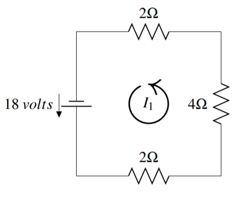
The jagged lines ( ) denote resistors and the numbers next to them give their resistance in ohms, written as \(\Omega\). The voltage source (
 ) causes the current to flow in the direction from the shorter of the two lines toward the longer (as indicated by the arrow). The current for a circuit is labeled \(I_k\).
In the above figure, the current \(I_1\) has been labeled with an arrow in the counter clockwise direction. This is an entirely arbitrary decision and we could have chosen to label the current in the clockwise direction. With our choice of direction here, we define a positive current to flow in the counter clockwise direction and a negative current to flow in the clockwise direction.
The goal of this section is to use the values of resistors and voltage sources in a circuit to determine the current. An essential theorem for this application is Kirchhoff’s law.
The sum of the resistance (\(R\)) times the amps (\(I\)) in the counter clockwise direction around a loop equals the sum of the voltage sources (\(V\)) in the same direction around the loop.
Kirchhoff’s law allows us to set up a system of linear equations and solve for any unknown variables. When setting up this system, it is important to trace the circuit in the counter clockwise direction. If a resistor or voltage source is crossed against this direction, the related term must be given a negative sign.
We will explore this in the next example where we determine the value of the current in the initial diagram.
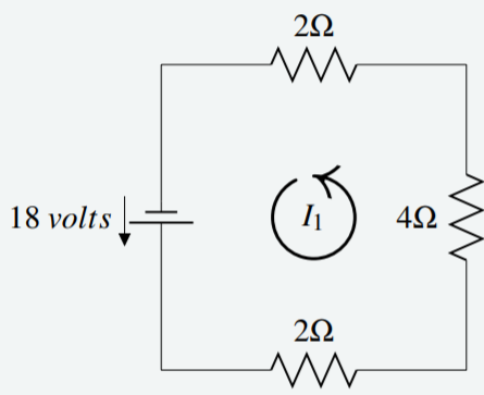
Applying Kirchhoff’s Law to the diagram below, determine the value for \(I_1\).
Solution
Begin in the bottom left corner, and trace the circuit in the counter clockwise direction. At the first resistor, multiplying resistance and current gives \(2I_1\). Continuing in this way through all three resistors gives \(2I_1 + 4I_1 + 2 I_1\). This must equal the voltage source in the same direction. Notice that the direction of the voltage source matches the counter clockwise direction specified, so the voltage is positive.
Therefore the equation and solution are given by \[\begin{aligned} 2I_1 + 4I_1 + 2 I_1 &= 18 \\ 8I_1 &= 18 \\ I_1 &= \frac{9}{4} A\end{aligned}\]
Since the answer is positive, this confirms that the current flows counter clockwise.
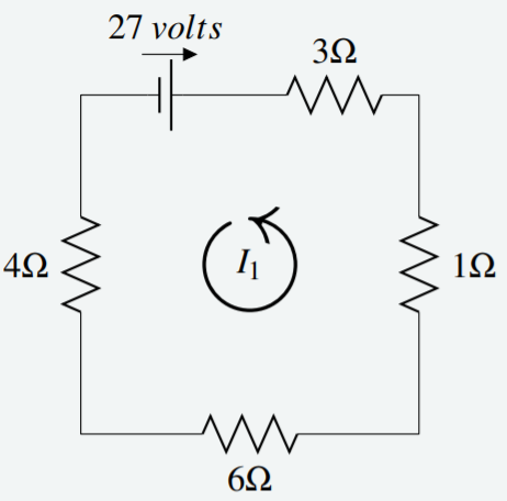
Applying Kirchhoff’s Law to the diagram below, determine the value for \(I_1\).
Solution
Begin in the top left corner this time, and trace the circuit in the counter clockwise direction. At the first resistor, multiplying resistance and current gives \(4I_1\). Continuing in this way through the four resistors gives \(4I_1 + 6I_1 + 1 I_1 + 3I_1\). This must equal the voltage source in the same direction. Notice that the direction of the voltage source is opposite to the counter clockwise direction, so the voltage is negative.
Therefore the equation and solution are given by \[\begin{aligned} 4I_1 + 6I_1 + 1 I_1 + 3I_1&= -27 \\ 14I_1 &= -27 \\ I_1 &= -\frac{27}{14} A\end{aligned}\]
Since the answer is negative, this tells us that the current flows clockwise.
A more complicated example follows. Two of the circuits below may be familiar; they were examined in the examples above. However as they are now part of a larger system of circuits, the answers will differ.
The diagram below consists of four circuits. The current (\(I_k\)) in the four circuits is denoted by \(I_{1},I_{2},I_{3},I_{4}\). Using Kirchhoff’s Law, write an equation for each circuit and solve for each current.
Solution
The circuits are given in the following diagram.
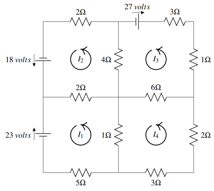
Starting with the top left circuit, multiply the resistance by the amps and sum the resulting products. Specifically, consider the resistor labeled \(2 \Omega\) that is part of the circuits of \(I_1\) and \(I_2\). Notice that current \(I_2\) runs through this in a positive (counter clockwise) direction, and \(I_1\) runs through in the opposite (negative) direction. The product of resistance and amps is then \(2 (I_2 - I_1) = 2I_2 - 2I_1\). Continue in this way for each resistor, and set the sum of the products equal to the voltage source to write the equation: \[2I_{2}-2I_{1}+4I_{2}-4I_{3}+2I_{2}=18\nonumber \] The above process is used on each of the other three circuits, and the resulting equations are:
Upper right circuit: \[4I_{3} - 4I_{2} + 6I_{3} - 6I_{4} + I_{3} + 3I_{3} = -27\nonumber \] Lower right circuit: \[3I_{4} + 2I_{4} + 6I_{4} - 6I_{3} + I_{4} - I_{1} = 0\nonumber \] Lower left circuit: \[5I_{1}+I_{1}-I_{4}+2I_{1}-2I_{2}=-23\nonumber \]
Notice that the voltage for the upper right and lower left circuits are negative due to the clockwise direction they indicate.
The resulting system of four equations in four unknowns is \[\begin{aligned} 2I_{2}-2I_{1}+4I_{2}-4I_{3}+2I_{2}&=18 \\ 4I_{3} - 4I_{2} + 6I_{3} - 6I_{4} + I_{3} + I_{3} &= -27 \\ 2I_{4} + 3I_{4} + 6I_{4} - 6I_{3} + I_{4} - I_{1} &= 0 \\ 5I_{1}+I_{1}-I_{4}+2I_{1}-2I_{2}&= -23\end{aligned}\] Simplifying and rearranging with variables in order, we have: \[\begin{aligned} -2I_{1}+8I_{2}-4I_{3}&=18 \\ - 4I_{2} + 14I_{3} - 6I_{4} &= -27 \\ -I_{1} - 6I_{3} + 12I_{4} &= 0 \\ 8I_{1}-2I_{2} - I_{4} &= -23\end{aligned}\] The augmented matrix is \[\left[ \begin{array}{rrrr|r} -2 & 8 & -4 & 0 & 18 \\ 0 & -4 & 14 & -6 & -27 \\ -1 & 0 & -6 & 12 & 0 \\ 8 & -2 & 0 & -1 & -23 \end{array} \right]\nonumber \]
The solution to this matrix is \[\begin{aligned} I_{1} &= -3 A\\ I_{2} &= \frac{1}{4} A\\ I_{3} &= -\frac{5}{2} A\\ I_{4} &= -\frac{3}{2} A\end{aligned}\]
This tells us that currents \(I_1, I_3,\) and \(I_4\) travel clockwise while \(I_2\) travels counter clockwise.